Product Overview
The LFZBJ7-11kV current transformer is an indoor wall-through epoxy cast-resin current transformer designed for medium-voltage switchgear. It is suitable for busbar connection, current measurement, electric energy metering, and relay protection in AC power systems. For international project documentation, the voltage class should be written as 11kV and 12kV class, with 10kV-class compatibility confirmed by insulation level, drawing and project specification.
The product adopts a wall-through mounting structure. The primary conductor or busbar connects through the current transformer body, while the secondary windings provide standardized low-current output for meters, protection relays and monitoring devices. The catalogue shows two closely related variants, LFZBJ7-10 and LFZBJ7-10L. For the website page, they can be integrated as one LFZBJ7-11kV product family, with the standard type and L-type distinguished mainly by installation length and outline dimensions.
This product is different from hollow ring-type cable/busbar CTs. It is more suitable for cabinet layouts that require a cast-resin wall-through body, busbar-side primary connection, extended primary terminals and a clearly separated secondary terminal block. It can support 5A, 1A or 2A secondary outputs, with metering and protection combinations such as 0.2/10P10, 0.5/10P10, 0.2/10P15 and 0.5/10P15.
Product Type
| Item | Specification |
|---|---|
| Product name | Indoor Wall-Through Epoxy Cast-Resin Current Transformer |
| Model series | LFZBJ7-11kV / LFZBJ7-10 / LFZBJ7-10L |
| Structure | Wall-through type, busbar connection, epoxy resin cast insulation |
| Voltage class | 11kV and 12kV class indoor medium-voltage systems |
| Rated insulation level | 12/42/75kV |
| Rated frequency | 50Hz |
| Rated secondary current | 5A, 1A or 2A |
| Rated primary current | 5A to 1200A reference range depending on variant and specification |
| Typical use | Current measurement, energy metering, relay protection, busbar feeder monitoring |
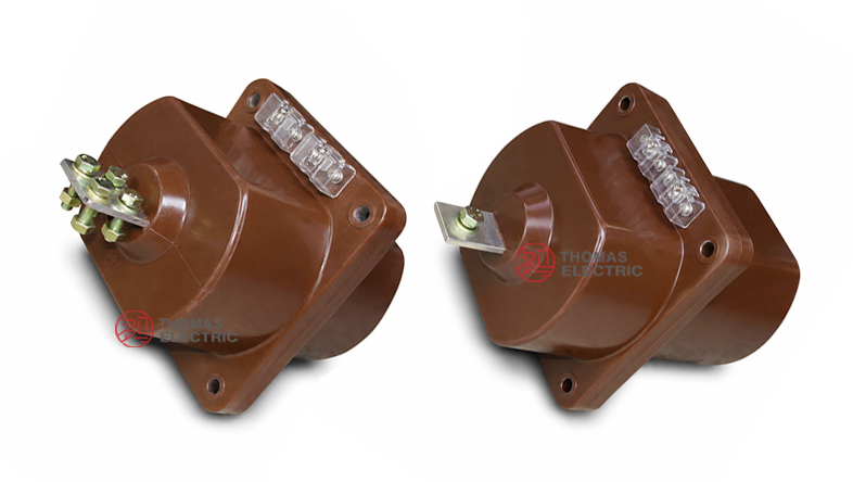
Product Display


The LFZBJ7 series has a compact wall-through cast-resin body with extended primary terminals, a square mounting flange and a front secondary terminal block. The standard type and L-type follow similar electrical principles, but the L-type has a longer body and is used when cabinet depth or busbar positioning requires additional installation length.
Applications
- 11kV and 12kV class indoor medium-voltage switchgear
- Fixed switchgear, metering panels, incoming cabinets and outgoing feeder panels
- Busbar-connected current measurement and energy metering circuits
- Relay protection circuits using 10P10 or 10P15 protection classes
- Wall-through cabinet installation where the CT passes through a panel or partition
- Retrofit projects requiring replacement of similar wall-through cast-resin CTs
Features
- Wall-through structure: Designed for through-panel installation in cabinet partitions and medium-voltage busbar systems.
- Busbar connection: Primary connection is arranged through both sides of the CT body for stable busbar connection.
- Epoxy cast-resin insulation: Resin casting supports insulation strength, mechanical stability and moisture resistance for indoor service.
- Standard and L-type variants: LFZBJ7-10 and LFZBJ7-10L can be selected according to cabinet depth and busbar layout.
- Flexible secondary output: 5A, 1A or 2A secondary output can be selected according to meter, relay and wiring burden.
- Metering and protection combinations: Supports 0.2 / 0.5 metering classes and 10P10 / 10P15 protection classes.
Principle
The LFZBJ7-11kV current transformer operates according to electromagnetic induction. When the primary current flows through the busbar or primary conductor path, magnetic flux is generated in the internal core. The secondary winding then induces a proportional low-current signal for meters, energy metering devices, protection relays or monitoring systems.
For measurement circuits, the transformer must maintain ratio accuracy and phase displacement within the rated burden. For protection circuits, the 10P-class winding must provide sufficient output under fault-current conditions. Correct selection of current ratio, secondary current, rated output and protection class is essential for reliable switchgear operation.
Model Designation
| Code | Meaning |
|---|---|
| L | Current transformer |
| F | Wall-through / through-type structure |
| Z | Epoxy resin casting insulation |
| B | Protection-class configuration available |
| J | Enhanced / reinforced cast-resin design reference |
| 7 | Design sequence code |
| 11kV | International voltage-class positioning for 11kV / 12kV switchgear |
| 10 / 10L | Catalogue variant references with different outline dimensions |
Technical Data
| Item | Specification |
|---|---|
| Rated voltage class | 11kV and 12kV class indoor systems; 10kV class compatibility by project confirmation |
| Rated insulation level | 12/42/75kV |
| Rated frequency | 50Hz |
| Rated secondary current | 5A, 1A or 2A |
| Rated primary current | 5A, 10A, 15A, 20A, 30A, 40A, 50A, 75A, 100A, 150A, 200A, 300A, 400A and up to 1200A by specification |
| Accuracy combinations | 0.2/10P10, 0.5/10P10, 0.2/10P15, 0.5/10P15, and multi-core combinations by order |
| Rated output | 10VA, 15VA, 20VA, 25VA or project-specific output according to ratio and accuracy class |
| Rated short-time thermal current | 0.7kA to 30kA reference range depending on current ratio and variant |
| Rated dynamic current | 1.75kA to 100kA reference range depending on current ratio and variant |
| Ambient temperature | -5°C to +55°C |
| Applicable standards | GB20840.2-2014, IEC61869-2:2012 and customer-specific requirements |
Selection Table
The selection data below combines the LFZBJ7-10 and LFZBJ7-10L catalogue information into one website-friendly table. Long cells are split into multiple lines to avoid layout overflow on product pages.
| Variant | Rated
Primary Current (A) |
Accuracy
Class Combination |
Rated
Output (VA) |
Short-Time
Thermal Current |
Dynamic
Current |
|---|---|---|---|---|---|
| LFZBJ7-10 | 5–40 | 0.2 / 10P10 0.5 / 10P10 |
0.2: 10 0.5: 10 10P: 15 |
0.7–4.4kA | 1.75–11kA |
| 50–100 | 0.2: 10 0.5: 10 10P: 15 |
5.5–15kA | 13.8–37.5kA | ||
| 150–200 | 0.2: 10 0.5: 10 10P: 15 |
20–28kA | 50–70kA | ||
| 300–400 | 0.2: 10 0.5: 10 10P: 15 |
30–40kA | 75–100kA | ||
| LFZBJ7-10L | 5–40 | 0.2 / 10P15 0.5 / 10P15 0.2 / 10P10 / 10P10 0.5 / 10P10 / 10P10 |
0.2: 10 0.5: 20 10P: 25 |
0.7–4.4kA | 1.75–11kA |
| 50–100 | 0.2: 10 0.5: 20 10P: 25 |
5.5–15kA | 13.8–37.5kA | ||
| 150–200 | 0.2: 10 0.5: 20 10P: 25 |
20–28kA | 50–70kA | ||
| 300–400 | 0.2: 10 0.5: 20 10P: 25 |
30–40kA | 75–100kA | ||
| 600–1200 | By agreement | By agreement | By agreement |
Note: Final ratio, rated output, thermal current, dynamic current and accuracy class shall be confirmed according to the approved drawing, nameplate and technical agreement.
Dimensions
| Variant | Overall Dimension Reference | Application Note |
|---|---|---|
| LFZBJ7-10 | Approx. 420±3mm length reference, compact wall-through body | Suitable for standard cabinet depth and medium-current wall-through installation. |
| LFZBJ7-10L | Approx. 450±3mm length reference, longer body variant | Suitable where additional installation length or larger busbar arrangement is required. |
| Mounting flange | Front mounting plate with four mounting holes and terminal block | Hole size, bolt distance and terminal position must be confirmed before cabinet production. |
| Weight | Approx. 22kg reference for catalogue variant | Actual weight depends on ratio, core configuration and selected structure. |
Terminals
The LFZBJ7 series uses a primary busbar or conductor connection with secondary terminals arranged on the resin body. The primary current direction is identified by P1. Secondary terminals are marked according to the ordered winding configuration, commonly including metering and protection outputs.
| Terminal | Function | Application Note |
|---|---|---|
| P1 / P2 | Primary terminals | Used for busbar or primary conductor connection and polarity reference. |
| 1S1 / 1S2 | First secondary winding | Usually used for metering or the first specified secondary core. |
| 2S1 / 2S2 | Second secondary winding | Usually used for relay protection or additional secondary circuit. |
| Grounding point | Protective grounding | Grounding shall follow the project wiring diagram and electrical safety requirements. |
Service Conditions
- Installation location: indoor medium-voltage switchgear
- Rated voltage: 11kV and 12kV class systems by project confirmation
- Rated frequency: 50Hz
- Rated secondary current: 5A, 1A or 2A by order
- Ambient temperature: -5°C to +55°C
- The installation environment should be non-explosive and free from corrosive gas, conductive dust, heavy pollution and abnormal condensation.
- For special environmental conditions, altitude, humidity or seismic requirements, technical confirmation is recommended before ordering.
Standards and Compliance
The LFZBJ7-11kV current transformer can be specified according to GB20840.2-2014, IEC61869-2:2012 and customer-specific requirements. Routine test documentation may include ratio verification, polarity check, accuracy test, insulation resistance test and power-frequency withstand test. For export projects, the product description should prioritize 11kV and 12kV class wording to match common international medium-voltage systems.
Installation and Dimensions

The LFZBJ7 series is designed for wall-through installation with busbar connection. Before switchgear production, the mounting plate position, wall opening, busbar hole, primary terminal clearance, secondary terminal direction, grounding point and maintenance space should be confirmed with the approved outline drawing. The LFZBJ7-10L version has a longer body than the standard LFZBJ7-10, so cabinet depth and busbar position must be checked carefully.
Safety Notes
- Confirm model variant, voltage class, current ratio, secondary current and accuracy class before production.
- Check mounting hole distance, wall opening, busbar clearance and primary terminal position before cabinet assembly.
- Connect primary and secondary terminals according to polarity marks and the approved wiring diagram.
- The CT secondary circuit must not be open-circuited while primary current is flowing.
- Before disconnecting meters or relays, short-circuit the secondary circuit with an approved shorting device.
- One point of the secondary circuit should be grounded according to project electrical safety practice.
- Installation and commissioning shall be performed by qualified medium-voltage electrical personnel.
Ordering Info
- Product model: LFZBJ7-11kV / LFZBJ7-10 / LFZBJ7-10L
- Voltage class: 11kV or 12kV class
- Rated primary current and rated secondary current: 5A, 1A or 2A
- Accuracy class combination and rated output for each secondary core
- Protection class requirement: 10P10, 10P15 or project-specific requirement
- Required short-time thermal current and dynamic current
- Variant requirement: standard type or longer L type
- Mounting drawing, busbar size, terminal direction and cabinet layout
- Applicable standard, test report and certificate requirements
- Quantity, label language, packaging and project documentation requirements
Selection Guide
- Confirm voltage class: Use 11kV and 12kV class wording for international projects, then confirm insulation level and standard requirements.
- Select model variant: Choose LFZBJ7-10 for standard wall-through installation or LFZBJ7-10L when a longer installation body is required.
- Select current ratio: Match the rated primary current to the actual feeder load, metering range and protection setting.
- Select secondary current: Use 5A for conventional circuits, 1A for lower burden, or 2A if required by the project device.
- Define core function: Use metering class for instruments and 10P class for protection relay circuits.
- Verify withstand ratings: Check short-time thermal current and dynamic current against switchgear fault level.
- Approve drawings: Confirm wall opening, mounting holes, busbar connection, terminal layout and cabinet depth before production.