Product Overview
The LZZBJ9-10LS/150 and LZZBJ9-10LS/150L current transformers are indoor epoxy cast-resin current transformers designed around a vertical busbar slot structure. Unlike conventional post-type CTs that mainly emphasize body width or multi-secondary configuration, this LS platform should be positioned as a switchgear CT for slot-mounted busbar installation, where the primary conductor passes through or is fixed within the upper slot area and the CT body provides insulation, support and secondary signal output.
The two models are suitable for 10 kV, 11 kV and 12 kV class indoor switchgear systems. The LZZBJ9-10LS/150 version covers wider current selection up to 2000 A, while the LZZBJ9-10LS/150L version is a longer-body variant for projects where the busbar connection and mounting dimension require the L-type structure. Both versions are used for current measurement, energy metering and relay protection, with 5 A or 1 A secondary current and selectable 0.2S, 0.2, 0.5, 5P and 10P accuracy combinations.
Product Type
| Item | Specification |
|---|---|
| Product name | Indoor Epoxy Cast-Resin Slot-Type Current Transformer |
| Model series | LZZBJ9-10LS/150 / LZZBJ9-10LS/150L |
| Structure | Indoor, epoxy cast-resin, fully enclosed vertical busbar slot structure |
| System voltage application | 10 kV, 11 kV and 12 kV class medium-voltage systems |
| Rated insulation level | 12/42/75 kV |
| Rated frequency | 50 Hz / 60 Hz |
| Rated secondary current | 5 A or 1 A |
| Rated primary current range | 10 A to 2000 A reference range according to model and technical data |
| Installation concept | Vertical slot / busbar-through type for indoor switchgear |
| Applications | Measurement, metering, relay protection and switchgear current monitoring |
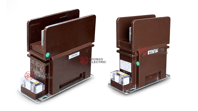
Product Display
 Epoxy Cast-Resin Slot-Type Current Transformer Thomas Electric")
 Epoxy Cast-Resin Slot-Type Current Transformer Thomas Electric")
Applications
- Indoor medium-voltage switchgear for 10 kV, 11 kV and 12 kV class systems
- Switchgear panels requiring vertical busbar slot CT installation
- Current measurement and energy metering circuits
- Relay protection circuits requiring 5P10, 5P20, 10P10, 10P15 or 10P20 classes
- Compact cabinet designs where the busbar passes through the CT slot area
- Projects requiring an LS-type or L-type slot structure instead of a standard post CT body
Features
- Slot-type positioning: The LS structure is designed for vertical busbar installation, making it different from standard post-type LZZBJ9 CT pages.
- Two structural options: LZZBJ9-10LS/150 is the standard LS slot-type version, while LZZBJ9-10LS/150L is the longer-body version for different cabinet layouts.
- Metering and protection combinations: Supports 0.2S, 0.2 and 0.5 measuring classes together with 5P and 10P protection classes.
- Epoxy cast-resin insulation: The dry-type resin body provides insulation, mechanical strength and indoor environmental resistance.
- Busbar-focused drawings: The outline drawings separate lower-current and higher-current layouts, helping engineers confirm busbar size and terminal position before production.
- 10 kV to 12 kV class application: Suitable for common 10 kV, 11 kV and 12 kV class switchgear systems with 12/42/75 kV insulation coordination.
Principle
The LZZBJ9-10LS/150 platform converts primary current into a proportional secondary current signal through electromagnetic induction. The primary busbar passes through or is fixed in the slot structure, and the CT core and secondary winding generate a 5 A or 1 A secondary output for measuring instruments, energy meters or protection relays.
Because the LS structure is closely related to busbar geometry, model selection should not be based only on current ratio and accuracy class. The busbar width, slot clearance, primary terminal hole position, cabinet depth, rated output and protection accuracy limit should be reviewed together. This is especially important when selecting between the standard LS/150 and the longer LS/150L structure.
Model Designation
| Code | Meaning |
|---|---|
| L | Current transformer |
| Z | Indoor type / support-type structure |
| Z | Epoxy resin cast insulation |
| B | Protection level available |
| J | Strengthened design |
| 9 | Design serial number |
| 10 | 10 kV catalogue voltage class; applicable to 10 kV, 11 kV and 12 kV class systems when insulation coordination is confirmed |
| LS | Slot-type / busbar-through structure code |
| 150 | 150 structure dimension code |
| L | Long-body structural variant for different busbar and cabinet layout requirements |
Technical Data
| Item | Specification |
|---|---|
| Model | LZZBJ9-10LS/150 / LZZBJ9-10LS/150L |
| System voltage application | 10 kV, 11 kV and 12 kV class systems |
| Rated insulation level | 12/42/75 kV |
| Rated frequency | 50 Hz / 60 Hz |
| Rated secondary current | 5 A or 1 A |
| LZZBJ9-10LS/150 rated primary current range | 10 A to 2000 A reference range according to supplied data |
| LZZBJ9-10LS/150L rated primary current range | 10 A to 1500 A reference range according to supplied data |
| Accuracy combinations | 0.2S/0.5, 0.2S/0.2S, 0.2/5P10, 0.2S/5P10, 0.5/5P10, 0.2/10P10, 0.2S/10P10, 0.5/10P10 and project-specific combinations |
| Rated output | 10/15, 15/15, 20/15, 20/20/15 and project-specific VA configurations |
| Rated short-time thermal current | 65 × I1n, 80 × I1n or 100 kA reference according to current ratio |
| Rated dynamic current | 2.5 × Ith or 250 kA reference according to technical table |
| Applicable standards | GB 20840.1-2010, GB 20840.2-2014, IEC 61869-2:2012 and special project requirements |
LS/150 Configuration
The LZZBJ9-10LS/150 version is the standard slot-type structure. It is suitable for current ratios from 10 A to 2000 A according to the supplied table and can be selected for both metering and protection circuits.
| Rated
Primary Current (A) |
Typical
Accuracy Combination |
Rated
Output (VA) |
Short-Time
Thermal Current |
Rated
Dynamic Current |
|---|---|---|---|---|
| 10–75 | 0.2S / 0.5 0.2S / 0.2S 0.2 / 5P10 0.2S / 5P10 0.5 / 5P10 0.2 / 10P10 0.2S / 10P10 0.5 / 10P10 |
10 / 15 | 65 × I1n | 162.5 × I1n |
| 100–400 | 10 / 15 | 80 × I1n | 200 × I1n | |
| 500–1000 | 15 / 15 | 80 × I1n | 200 × I1n | |
| 1250–1500 | 20 / 15 | 100 kA | 250 kA | |
| 2000 | 20 / 15 | 100 kA | 250 kA |
LS/150L Configuration
The LZZBJ9-10LS/150L version is the long-body slot-type variant. It is suitable for projects where the busbar layout or switchgear cabinet requires a longer LS body and a different primary terminal spacing.
| Rated
Primary Current (A) |
Typical
Accuracy Combination |
Rated
Output (VA) |
Short-Time
Thermal Current |
Rated
Dynamic Current |
|---|---|---|---|---|
| 10–75 | 0.2S / 0.5 / 10P10 0.2S / 0.5(S) / 10P20 Project-specific combinations |
10 / 15 / 15 | 65 × I1n | 2.5 × Ith |
| 100–400 | 10 / 15 / 15 | 80 × I1n | 2.5 × Ith | |
| 500–1000 | 10 / 15 / 15 | 80 × I1n | 2.5 × Ith | |
| 1250 | 20 / 20 / 15 | 100 kA | 250 kA | |
| 1500 | 20 / 20 / 15 | 100 kA | 250 kA |
Note: The above values are arranged from the supplied technical information for website selection reference. Final ratio, secondary current, rated output, accuracy class, short-time thermal current, dynamic current and terminal markings shall follow the nameplate, approved drawing and factory test report.
Busbar Layout
The LS structure must be selected with the busbar layout. The supplied drawings show different dimensional references for lower-current and higher-current ranges. The primary busbar slot, terminal hole position and cabinet clearance shall be confirmed before production.
| Model | Current Range | Primary Layout Reference |
Design Focus |
|---|---|---|---|
| LZZBJ9-10LS/150L | I1n: 10–1000 A | Long-body lower-current slot layout | Confirm vertical slot clearance, primary contact position and cabinet depth. |
| LZZBJ9-10LS/150L | I1n: 1250–1500 A | Long-body high-current terminal layout | Confirm busbar hole spacing and primary conductor contact surface. |
| LZZBJ9-10LS/150 | 10 A ≤ I1n < 1250 A | Standard LS lower-current layout | Used for standard slot-type metering/protection applications. |
| LZZBJ9-10LS/150 | 1250 A ≤ I1n ≤ 2000 A | Standard LS high-current layout | Confirm primary busbar plate size and bolt-hole arrangement. |
Terminals
Primary terminals are marked as P1 / P2. Secondary terminals are arranged in the lower terminal block according to the specified secondary cores. For LS-type CTs, correct primary busbar direction and slot alignment are important for both electrical performance and mechanical assembly.
| Terminal Area | Function | Engineering Note |
|---|---|---|
| P1 / P2 | Primary busbar direction | Connect according to the switchgear wiring diagram and approved drawing. |
| Secondary terminal block | Metering and protection output | Terminal marking depends on the selected secondary configuration. |
| Grounding point | Safety grounding | Grounding shall follow switchgear requirements. |
| Shorting device | Secondary maintenance safety | Short-circuit the secondary circuit before disconnecting instruments or relays. |
Service Conditions
- Installation location: indoor medium-voltage switchgear
- System voltage: 10 kV, 11 kV and 12 kV class networks
- Rated frequency: 50 Hz / 60 Hz
- Rated secondary current: 5 A or 1 A
- Ambient temperature: -5°C to +40°C for LS/150L sample data; -25°C to +40°C for LS/150 sample data
- The installation environment should be free from severe vibration, conductive dust, corrosive gas, explosive medium, heavy pollution and abnormal condensation.
- For slot-type installation, busbar alignment and clearance should be checked before energizing the switchgear.
Standards and Compliance
The LZZBJ9-10LS/150 and LZZBJ9-10LS/150L current transformers can be supplied according to GB 20840.1-2010, GB 20840.2-2014, IEC 61869-2:2012 and special project requirements. For international product pages, the series should be described as indoor epoxy cast-resin slot-type current transformers for 10 kV, 11 kV and 12 kV class switchgear. Routine inspection generally includes ratio test, polarity verification, accuracy test, dielectric withstand test, insulation inspection and appearance inspection.
Installation and Dimensions
 Epoxy Cast-Resin Slot-Type Current Transformer Thomas Electric")
The LS/150 and LS/150L structures use a vertical busbar slot arrangement with a lower secondary terminal box and base mounting holes. Compared with standard rectangular post-type CTs, this platform requires more attention to the primary conductor route through the slot area. The approved outline drawing must be used before cabinet design, copper busbar processing or replacement installation.
Dimensions
| Item | Dimension / Note |
|---|---|
| Structure platform | LS/150 slot-type busbar platform |
| Model variants | Standard LS/150 and long-body LS/150L |
| Primary installation | Vertical busbar slot / primary plate connection according to drawing |
| Secondary terminal area | Lower secondary terminal block |
| Mounting base | Base mounting holes according to outline drawing |
| Drawing confirmation | Required before switchgear production, replacement or busbar fabrication |
Safety Notes
- Confirm whether the project requires LZZBJ9-10LS/150 or LZZBJ9-10LS/150L before ordering.
- Check the busbar slot size, busbar thickness, primary terminal hole position and cabinet clearance before production.
- Confirm current ratio, secondary current, rated output and accuracy class before wiring.
- Connect P1/P2 according to the polarity marking and switchgear wiring diagram.
- The secondary circuit of a current transformer must not be open-circuited when the primary circuit is energized.
- Before disconnecting instruments or relays, short-circuit the corresponding secondary circuit through a proper shorting device.
- Installation and maintenance shall be performed by qualified medium-voltage electrical personnel.
Ordering Info
- Product model: LZZBJ9-10LS/150 or LZZBJ9-10LS/150L
- System voltage: 10 kV, 11 kV or 12 kV
- Rated primary current and rated secondary current
- Accuracy class combination and rated output for each secondary circuit
- Busbar slot layout, primary terminal hole size and mounting dimension requirement
- Rated insulation level and applicable IEC / GB standard
- Required short-time thermal current and rated dynamic current
- Switchgear layout, cabinet clearance and primary terminal direction
- Quantity, certificates, routine test reports, labeling and packaging requirements
Selection Guide
- Confirm slot-type requirement: Select the LS platform when the switchgear requires vertical busbar slot installation instead of a conventional post CT structure.
- Select LS or L version: Choose LS/150 for standard layouts or LS/150L when a longer body and different busbar spacing are required.
- Check voltage class: Use the series for 10 kV, 11 kV and 12 kV class systems when insulation coordination is confirmed.
- Define accuracy combination: Specify measurement and protection classes such as 0.2S, 0.5, 5P or 10P according to the circuit function.
- Verify busbar dimensions: Confirm slot clearance, terminal hole spacing, conductor size and cabinet mounting space before production.
- Check thermal and dynamic current: Match the CT withstand ratings with the switchgear fault level.
- Approve final drawing: Confirm outline dimensions, terminal diagram, nameplate data and routine test requirements before manufacturing.