Product Overview
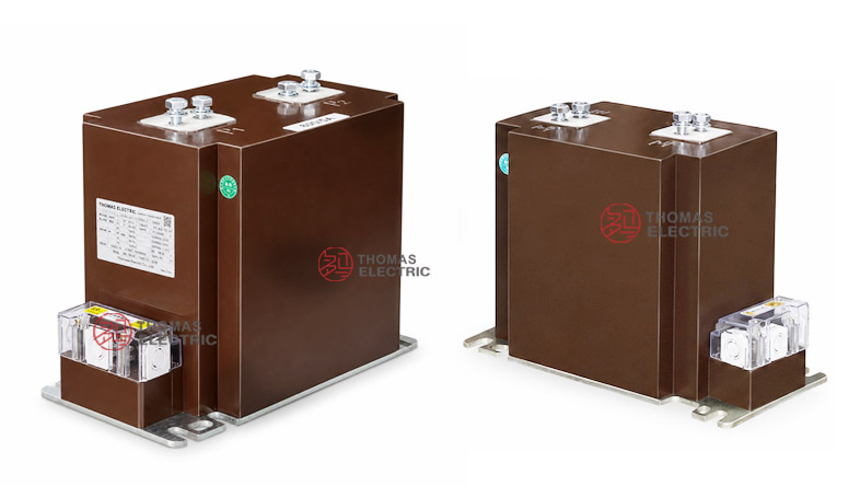
The LZZBJ9-12/185b/2S current transformer is an indoor epoxy cast-resin, fully enclosed support-type current transformer for medium-voltage switchgear. It is designed for current measurement, electric energy metering, feeder monitoring and relay protection in 10kV, 11kV and 12kV class indoor AC distribution systems.
The 185b structure is positioned between compact 150b designs and wider multi-secondary body designs. It provides more internal insulation space and primary-terminal clearance than compact CT bodies, while keeping a practical size for indoor switchgear installation. This makes it suitable for projects where the CT must balance cabinet space, insulation distance, secondary terminal access and short-circuit withstand requirements.
The 2S secondary schematic is intended for two independent secondary circuits. In typical engineering use, one secondary core can be assigned to measurement or energy metering, while the other can be assigned to feeder relay protection. Final selection shall be confirmed according to current ratio, 1A or 5A secondary output, accuracy class, rated output, short-time thermal current, dynamic current, terminal marking and approved outline drawing.
Product Type
| Item | Specification |
|---|---|
| Product name | Indoor Epoxy Cast-Resin Current Transformer |
| Model series | LZZBJ9-12/185b/2S |
| Structure | Indoor, fully enclosed, support-type, epoxy cast-resin insulated structure |
| Voltage class | 10kV, 11kV and 12kV class medium-voltage systems |
| Rated insulation level | 12/42/75kV |
| Rated frequency | 50Hz / 60Hz |
| Secondary current | 5A or 1A |
| Secondary structure | 2S dual-secondary configuration |
| Installation | Indoor support-type switchgear installation |
| Applications | Current measurement, energy metering, feeder protection and monitoring |
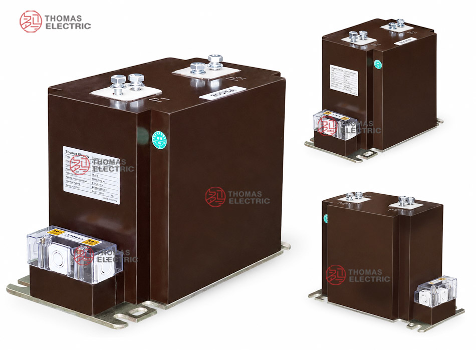
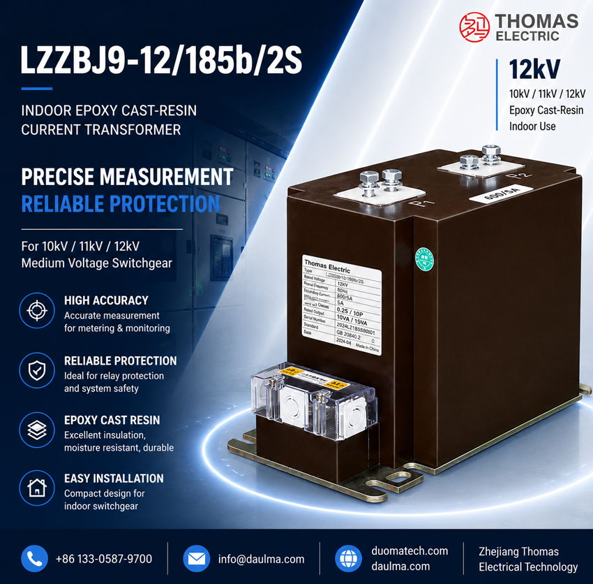
Product Display
Applications
- Indoor 10kV, 11kV and 12kV class medium-voltage switchgear
- Incoming and outgoing feeder panels requiring two CT secondary functions
- Energy metering panels with a dedicated measurement core
- Feeder relay protection circuits with separate protection-core output
- Industrial substations, utility distribution rooms and commercial MV switchboards
- Switchgear projects requiring more terminal clearance than compact 150b structures
Features
- 185b body structure: Provides a balanced body width for switchgear where compact installation and improved terminal clearance are both required.
- Dual-secondary design: The 2S configuration supports two independent secondary circuits, commonly used for measurement plus protection.
- Epoxy resin insulation: The full cast-resin body improves insulation stability, mechanical protection and resistance to indoor humidity and contamination.
- 12kV IEC-style application: Designed for international 10kV, 11kV and 12kV class systems with 12/42/75kV insulation coordination.
- Wide ratio selection: Sample data includes low-current and high-current ranges up to 2500A, subject to project agreement and nameplate confirmation.
- Practical switchgear wiring: The two-secondary layout simplifies terminal identification compared with four-secondary CTs while still supporting metering and protection separation.
Principle
The LZZBJ9-12/185b/2S current transformer works by electromagnetic induction. Primary current flowing through the primary path generates magnetic flux in the CT core, and the secondary winding delivers a proportional current signal to the connected meter, relay or monitoring device. The epoxy resin body provides insulation between the medium-voltage primary side and the low-voltage secondary circuits.
For the 2S arrangement, the two secondary circuits should be specified separately. A metering or measuring core should be checked for accuracy and burden, while a protection core should be checked for protection accuracy class, fault-current behavior and relay setting coordination. This separation helps reduce selection errors in medium-voltage switchgear projects.
Model Designation
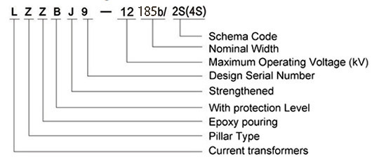
The model code can be interpreted as follows:
| Code | Meaning |
|---|---|
| L | Current transformer |
| Z | Indoor type / support structure |
| Z | Epoxy resin casting insulation |
| B | Protection level available |
| J | Strengthened design |
| 9 | Design serial number |
| 12 | 12kV class maximum operating voltage |
| 185b | Nominal width / structure dimension code |
| 2S | Dual-secondary schematic code |
Technical Data
| Item | Specification |
|---|---|
| Rated voltage class | 10kV, 11kV and 12kV class indoor systems |
| Rated insulation level | 12/42/75kV |
| Rated frequency | 50Hz / 60Hz |
| Rated primary current | 5A to 2500A reference range according to sample data; special ratios by agreement |
| Rated secondary current | 5A or 1A |
| Accuracy combination | 0.2S/10P, 0.2/10P, 0.5/10P, 0.2S/10P15, 0.5/10P20 and project-specific metering/protection combinations |
| Rated output | 10/20, 10/30, 15/20, 20/20, 20/30 or project-specific VA configuration |
| Ambient temperature | -5°C to +40°C |
| Insulating medium | Epoxy resin |
| Installation type | Indoor support-type / switchgear installation |
| Applicable standards | GB 20840.2-2014, IEC 61869-2:2012 and special project requirements |
Terminals
The 2S schematic indicates two secondary circuits. Typical terminal markings include P1 / P2 for the primary side and 1S1 / 1S2, 2S1 / 2S2 for secondary circuits. Final terminal identification shall follow the approved drawing, wiring diagram and product nameplate.
| Terminal Marking |
Function | Application Note |
|---|---|---|
| P1 / P2 | Primary terminals | Primary current direction and busbar connection shall follow the switchgear wiring diagram. |
| 1S1 / 1S2 | First secondary core | Usually assigned to measurement, metering or monitoring. |
| 2S1 / 2S2 | Second secondary core | Usually assigned to relay protection or an additional measurement circuit. |
| Shorting terminal | Secondary circuit safety | Recommended for safe maintenance and relay replacement operations. |
Selection Table
The following table summarizes typical 185b/2S ratio ranges and technical selection data. Long accuracy and rated-output values are wrapped into multiple lines for website readability.
| Rated
Primary Current (A) |
Accuracy
Class Combination |
Rated
Output (VA) |
Short-Time
Thermal Current |
Rated
Dynamic Current (kA) |
|---|---|---|---|---|
| 5 | 0.2S / 10P 0.2 / 10P 0.5 / 10P 0.2S / 10P15 0.5 / 10P20 |
10 / 20 10 / 30 15 / 20 |
1.0kA | 2.5 |
| 10 | 2.0kA | 5 | ||
| 20 | 6.0kA | 15 | ||
| 30 | 8.0kA | 20 | ||
| 40, 50 | 10 / 20 10 / 30 20 / 20 20 / 30 |
16kA | 40 | |
| 75, 100 | 31.5kA | 80 | ||
| 150–300 | 45kA | 112.5 | ||
| 400–800 | 80kA | 160 | ||
| 1000–2500 | 100kA | 160 |
Note: The above values are for technical selection reference. If project requirements exceed the listed scope, final parameters shall be confirmed by agreement between manufacturer and purchaser. Nameplate data, approved drawings and factory test reports shall prevail.
Structure Reference
| Structure | Engineering Purpose |
Selection Note |
|---|---|---|
| 185b | Medium support body with improved terminal clearance | Suitable for switchgear requiring more wiring and busbar clearance than compact 150b models. |
| 2S | Two independent secondary circuits | Suitable for separating measurement and protection functions. |
| 12kV class | International MV switchgear voltage class | Used for 10kV, 11kV and 12kV class power systems. |
Service Conditions
- Installation location: indoor medium-voltage switchgear
- System voltage: 10kV, 11kV and 12kV class networks
- Rated frequency: 50Hz / 60Hz
- Ambient temperature: -5°C to +40°C
- The installation environment should be free from severe vibration, conductive dust, corrosive gas, explosive medium, heavy pollution and abnormal condensation.
- For high altitude, humid, coastal, high-pollution or special switchgear conditions, technical confirmation is required before ordering.
Standards and Compliance
The LZZBJ9-12/185b/2S current transformer can be supplied according to GB 20840.2-2014, IEC 61869-2:2012 and special project requirements. For IEC-oriented international projects, it can be positioned as a 12kV class indoor epoxy cast-resin CT with 12/42/75kV insulation coordination. Routine tests normally include ratio test, polarity verification, accuracy test, dielectric withstand test and appearance inspection.
Installation and Dimensions
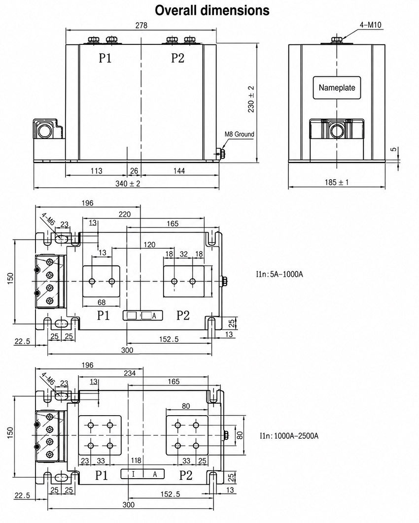
The product adopts an indoor support-type structure with top primary terminals and lower secondary terminal arrangement. The 185b body requires cabinet verification for primary terminal spacing, busbar routing, base fixing holes and secondary terminal access. The approved outline drawing shall be used before switchgear production or replacement.
Dimensions
| Item | Dimension / Note |
|---|---|
| Structure code | 185b support-type design |
| Secondary schematic | 2S dual-secondary arrangement |
| Primary terminal arrangement | Confirmed according to current ratio and approved drawing |
| Secondary terminal arrangement | Lower terminal block / terminal box according to drawing |
| Mounting holes | Confirmed according to outline drawing |
| Drawing confirmation | Required before switchgear production or replacement |
Safety Notes
- Confirm model, current ratio, secondary current, accuracy combination, rated output and insulation level before installation.
- Check mounting space, busbar connection, primary terminal position, secondary terminal layout and phase clearance before assembly.
- Confirm whether each secondary circuit is used for metering, measurement or protection before wiring.
- Connect P1/P2 and secondary terminals according to polarity markings and the project wiring diagram.
- The secondary circuit of a current transformer must not be open-circuited when the primary circuit is energized.
- Before disconnecting meters or relays, short-circuit the corresponding secondary circuit through an approved shorting terminal block.
- Installation and maintenance shall be performed by qualified medium-voltage electrical personnel.
Ordering Info
- Product model: LZZBJ9-12/185b/2S
- Rated primary current and rated secondary current
- Accuracy class combination and rated output for each secondary core
- Rated insulation level and applicable IEC / GB standard
- Required short-time thermal current and dynamic current
- Secondary core function, terminal marking and wiring diagram requirement
- Switchgear layout, mounting dimensions and primary terminal direction
- Quantity, certificates, routine test reports, labeling and packaging requirements
Selection Guide
- Confirm structure: Use LZZBJ9-12/185b/2S when the switchgear requires a medium-width 185b support CT with two secondary outputs.
- Define secondary functions: Assign the first and second cores to measurement, metering or protection before selecting accuracy classes.
- Select ratio: Choose rated primary current according to feeder load, metering range and relay setting.
- Check burden: Calculate meter burden, relay burden and secondary cable resistance for each core.
- Verify protection duty: Confirm 10P or other protection requirements according to relay settings and system fault level.
- Review cabinet fit: Confirm busbar spacing, terminal clearance, mounting holes and secondary wiring space.
- Approve documentation: Confirm outline drawing, terminal diagram, nameplate data and test certificate requirements before production.