Product Overview
The LAJ-10 / LFZBJ-10 current transformer is an indoor epoxy cast-resin wall-through current transformer designed for medium-voltage switchgear applications. These two model references can be combined into one product family because both are used for current measurement, electric energy metering, and relay protection in indoor AC power systems. For international project documentation, the voltage class should be expressed as 10kV, 11kV and 12kV class, with final selection confirmed by insulation level, system voltage, and project technical requirements.
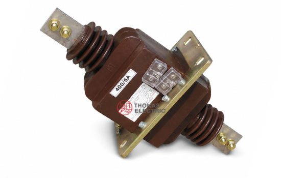
The LAJ-10 structure shown in the catalogue is an indoor epoxy cast-resin current transformer with primary conductors extending from both sides and a wall-mounted installation plate. It is suitable for applications where the CT is installed through a switchgear wall or mounting panel. The LFZBJ-10 reference from the existing product page belongs to the same wall-mounted cast-resin CT family, with differences mainly in structure details, protection configuration, and installation layout. Combining them into one product page helps present the series as a complete indoor wall-through current transformer solution rather than separating highly similar models into duplicated pages.
The product is designed for medium-voltage cabinets where the primary conductor passes through or connects across the transformer body, while the secondary winding provides a standardized 5A or 1A signal to meters, protection relays, and monitoring devices. Depending on the current rating and selected configuration, the series can support metering classes such as 0.2S / 0.2 / 0.5 and protection classes such as 10P10 or 10P15.
Product Type

| Item | Specification |
|---|---|
| Product name | Indoor Wall-Through Epoxy Cast-Resin Current Transformer |
| Model series | LAJ-10 / LFZBJ-10 |
| Structure | Wall-through type, epoxy resin cast insulation, indoor installation |
| Voltage class | 10kV, 11kV and 12kV class indoor medium-voltage systems |
| Rated insulation level | 12/42/75kV |
| Rated frequency | 50Hz; 60Hz available by project confirmation |
| Rated secondary current | 5A or 1A |
| Rated primary current | 5A to 1000A reference range; extended or customized ratios by agreement |
| Typical use | Current measurement, energy metering, relay protection, switchgear monitoring |
Product Display


The LAJ-10 / LFZBJ-10 series adopts a compact wall-mounted structure. The primary side is arranged across the transformer body, and the secondary terminals are located on the resin body for wiring to measuring instruments or protection relays. The catalogue image shows an integrated mounting plate, epoxy cast body, primary terminals on both sides, secondary terminal block, grounding point, and hole dimensions for cabinet installation.
Applications
- 10kV, 11kV and 12kV class indoor medium-voltage switchgear
- Fixed metal-enclosed switchgear, metering cabinets, incoming panels, and outgoing feeder panels
- Current measurement and electric energy metering circuits
- Relay protection circuits requiring 10P10 or 10P15 protection performance
- Wall-through CT installation where the transformer body is mounted on a switchgear partition or panel
- Replacement or retrofit projects where LAJ-10 and LFZBJ-10 type installation structures must be matched with existing cabinet openings
Features
- Combined LAJ-10 / LFZBJ-10 product family: Both models are presented together because they belong to the same indoor wall-through epoxy cast-resin CT application range.
- Wall-through cabinet installation: The structure is suitable for mounting through switchgear panels or cabinet partitions, with primary conductors arranged on both sides.
- Epoxy cast-resin insulation: The resin body supports insulation strength, mechanical stability, moisture resistance, and compact indoor installation.
- Metering and protection cores: The product can be configured for measurement accuracy or relay protection according to the selected accuracy class combination.
- Primary and secondary terminal clarity: Primary terminals and secondary terminals are arranged for practical field wiring, polarity checking, and maintenance access.
- International voltage expression: The product page uses 10kV, 11kV and 12kV class wording to support export markets and international switchgear projects.
Principle
The LAJ-10 / LFZBJ-10 current transformer operates by electromagnetic induction. The primary current flows through the primary conductor path and generates magnetic flux in the internal core. The secondary winding then outputs a proportional low-current signal, usually 5A or 1A, for meters, energy metering devices, protection relays, or monitoring systems.
For metering circuits, the CT must maintain ratio and phase accuracy within the rated burden. For protection circuits, the protection core must maintain a dependable secondary output under fault-current conditions. Correct selection of current ratio, secondary current, accuracy class, rated output, short-time thermal current, and dynamic current is essential for reliable measurement and protection performance.
Model Designation
| Code | Meaning |
|---|---|
| L | Current transformer |
| A | Wall-through / bulkhead-type structure |
| J | Design sequence or enhanced output series reference |
| 10 | 10kV class model reference, used for 10kV, 11kV and 12kV class project documentation by confirmation |
| LFZBJ-10 | Related epoxy cast-resin wall-mounted CT designation with protection-class configuration |
Technical Data
| Item | Specification |
|---|---|
| Rated voltage class | 10kV class; suitable for 10kV, 11kV and 12kV class indoor systems by project confirmation |
| Rated insulation level | 12/42/75kV |
| Rated frequency | 50Hz; 60Hz by agreement |
| Rated secondary current | 5A or 1A |
| Rated primary current | 5A, 10A, 20A, 50A, 100A, 150A, 200A, 300A, 400A, 500A, 600A, 800A, 1000A reference values |
| Accuracy classes | 0.2S, 0.2, 0.5, 10P10, 10P15 according to configuration |
| Rated output | 10VA, 15VA, 20VA or project-specific output depending on ratio and accuracy class |
| Rated short-time thermal current | 90 x I1n or kA-level values according to current ratio and project specification |
| Rated dynamic current | 200 x I1n or kA-level values according to current ratio and project specification |
| Ambient temperature | -5°C to +55°C reference for LAJ-10 sample; project conditions to be confirmed |
| Applicable standards | GB20840.2-2014, IEC61869-2:2012, and customer-specific requirements |
Selection Table
The following selection table combines the LAJ-10 catalogue data and LFZBJ-10 product-page selection logic. Long headers are wrapped into multiple lines to keep the table suitable for responsive website pages.
| Rated Primary Current (A) |
Accuracy Class Combination |
Rated Output (VA) |
Thermal Current Reference |
Dynamic Current Reference |
|---|---|---|---|---|
| 5-200 | 0.2S / 10P10 0.5 / 10P10 0.2S / 10P15 0.5 / 10P15 |
0.2S: 10 0.5: 10 10P10: 15 10P15: 15 |
90 x I1n | 200 x I1n |
| 300-400 | 0.2S: 10 0.5: 10 10P10: 15 10P15: 15 |
24.5kA reference | 44kA reference | |
| 500 | 0.2S: 10 0.5: 10 10P10: 20 10P15: 15 |
32kA reference | 80kA reference | |
| 600 | 0.2S: 10 0.5: 10 10P10: 20 10P15: 15 |
32kA reference | 80kA reference | |
| 800-1000 | 0.2S: 10 0.5: 10 10P10: 20 10P15: 15 |
63kA reference | 100kA reference |
Note: The values above are for preliminary product-page selection. Final ratio, rated output, thermal current, dynamic current and accuracy class shall be confirmed according to the nameplate, approved drawing and technical agreement.
Dimensions
| Item | LAJ-10 Reference | LFZBJ-10 Reference |
|---|---|---|
| Installation type | Wall-through mounting with primary terminals on both sides | Wall-mounted / bulkhead-type epoxy cast-resin CT structure |
| Overall length | Approx. 510mm reference from catalogue drawing | According to selected outline drawing and current ratio |
| Mounting plate | Approx. 260mm wide central mounting plate reference | Cabinet opening and mounting plate to be confirmed by drawing |
| Hole dimension | 160mm x 220mm reference with 4-Ø14 mounting holes | According to selected variant and cabinet requirement |
| Weight | Approx. 19.2kg reference | Subject to final selected structure |
Terminals
The LAJ-10 / LFZBJ-10 series should be wired according to the approved terminal diagram and polarity marks. The primary terminals are arranged on the two sides of the transformer body, while the secondary terminal block is located near the cast-resin body or mounting base for connection to meters and relays.
| Terminal | Function | Application Note |
|---|---|---|
| P1 / P2 | Primary terminals | Used to identify primary current direction and polarity reference. |
| 1S1 / 1S2 | First secondary winding | Normally used for metering or the first specified secondary core. |
| 2S1 / 2S2 | Second secondary winding | Used for protection or an additional secondary output when configured. |
| Grounding point | Protective grounding | Grounding shall follow project wiring and local electrical safety practice. |
Service Conditions
- Installation location: indoor medium-voltage switchgear
- Rated voltage: 10kV, 11kV and 12kV class systems by project confirmation
- Rated frequency: 50Hz; 60Hz by agreement
- Ambient temperature: -5°C to +55°C reference for the LAJ-10 sample
- Altitude, humidity, pollution level and condensation conditions should be confirmed according to the project environment.
- The installation environment should be free from severe vibration, corrosive gas, explosive medium, conductive dust and insulation-damaging contamination.
Standards and Compliance
The LAJ-10 / LFZBJ-10 current transformer page can be aligned with GB20840.2-2014, IEC61869-2:2012 and customer-specific requirements. The existing product reference also mentions the earlier GB1208 and IEC60044-1 family of current-transformer standards. For new international product pages, IEC61869 wording is preferred, while older standard references may be kept as legacy compatibility notes when required by the customer.
Installation and Dimensions

This series is intended for indoor wall-through or bulkhead-type installation. Before cabinet production, the mounting plate position, hole dimension, primary conductor route, terminal direction, insulation clearance, and maintenance space must be confirmed with the approved outline drawing. For retrofit projects, the LAJ-10 and LFZBJ-10 outlines should be checked carefully because similar electrical ratings may still have different installation dimensions.
Safety Notes
- Confirm model, voltage class, current ratio, secondary current, accuracy class and rated output before production.
- Check wall-through opening, primary terminal clearance, secondary terminal access and grounding position before switchgear assembly.
- Connect primary and secondary terminals according to the approved wiring diagram and polarity marks.
- The CT secondary circuit must not be open-circuited while primary current is flowing.
- Before disconnecting meters or relays, short-circuit the secondary circuit with an approved shorting device.
- One point of the secondary circuit should be grounded according to project electrical safety requirements.
- Installation and commissioning shall be performed by qualified medium-voltage electrical personnel.
Ordering Info
- Product model: LAJ-10 / LFZBJ-10
- System voltage class: 10kV, 11kV or 12kV class
- Rated primary current and rated secondary current: 5A or 1A
- Accuracy class combination and rated output for each secondary core
- Required protection class: 10P10, 10P15 or project-specific requirement
- Rated short-time thermal current and rated dynamic current
- Installation drawing, hole dimension, terminal direction and switchgear layout
- Applicable standard, routine test report and certificate requirements
- Quantity, label language, packaging and project documentation requirements
Selection Guide
- Confirm voltage class: Use the international wording 10kV, 11kV and 12kV class, then confirm the required insulation level with the project specification.
- Select model reference: Use LAJ-10 / LFZBJ-10 as one combined product family, while confirming the exact structure by drawing.
- Select current ratio: Choose the primary current according to load current, metering range and relay protection setting.
- Define secondary output: Select 5A for traditional systems or 1A where lower burden or longer secondary wiring is required.
- Choose accuracy: Use 0.2S / 0.2 / 0.5 for metering and 10P10 / 10P15 for protection.
- Verify withstand current: Confirm thermal and dynamic current ratings against the switchgear fault level.
- Approve dimensions: Check wall opening, primary terminals, secondary terminal block and mounting holes before cabinet production.