Product Overview
The LDZB(J)7-10(L) / TPOL-10 Type current transformer is an indoor wall-through epoxy cast-resin current transformer designed for medium-voltage switchgear, busbar systems and distribution panels. It is used for current measurement, electric energy metering, relay protection, control and secondary-circuit isolation in AC power systems with rated frequency of 50Hz or 60Hz.
This product is positioned as a TPOL-10 equivalent / replacement type for projects that require a Russian-style pass-through current transformer structure, while using international documentation for 11kV and 12kV class switchgear. The transformer is suitable for installation through switchgear partitions, distribution devices and busbar compartments. The primary conductor is connected through the transformer body, and the secondary windings provide standard 5A or 1A output signals to meters, protection relays and automation devices.
The LDZB(J)7-10(L) series includes a standard type and a longer L-type version. Both follow the same wall-through cast-resin design concept, but the L-type provides a longer body and different installation length for cabinet layouts requiring additional depth, busbar positioning or multiple secondary winding arrangements. For export projects, the product can be specified as an 11kV / 12kV indoor wall-through epoxy cast-resin CT aligned with IEC 61869-2 technical requirements.
Product Type
| Item | Specification |
|---|---|
| Product name | Indoor Wall-Through Epoxy Cast-Resin Current Transformer |
| Model series | LDZB(J)7-10(L) / TPOL-10 Type |
| Structure | Wall-through / pass-through type, epoxy resin cast insulation, indoor installation |
| Voltage class | 11kV and 12kV class indoor medium-voltage systems |
| Rated insulation level | 12/42/75kV, subject to final project specification |
| Rated frequency | 50Hz or 60Hz |
| Rated secondary current | 5A or 1A; 2A available by project requirement |
| Rated primary current | Typical range from 20A to 2000A depending on design and order requirement |
| Core configuration | Measurement, metering, protection, dual protection or multi-secondary winding options |
| Typical use | Current measurement, energy metering, relay protection, control and automation circuits |
Product Display
7-10L, TPOL-10 Wall-Through Cast-Resin Current Transformer Thomas Electric")
7-10L, TPOL-10 Wall-Through Cast-Resin Current Transformer Thomas Electric")
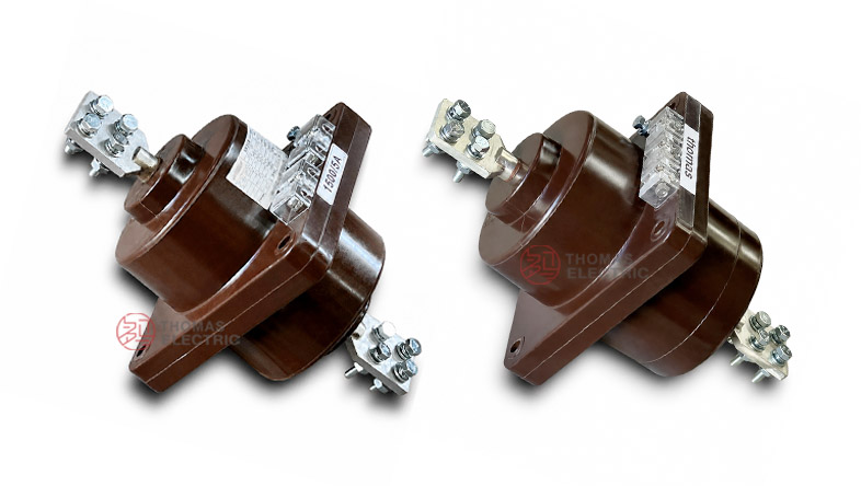
The LDZB(J)7-10(L) / TPOL-10 Type current transformer has a compact epoxy cast-resin body, a wall-through mounting flange, primary terminals on both sides, and a secondary terminal block on the resin body. The standard version is suitable for common cabinet installation, while the L-type version provides a longer body for projects requiring a different installation depth or busbar arrangement.
Applications
- 11kV and 12kV class indoor medium-voltage switchgear
- Russian TPOL-10 replacement projects and CIS-market switchgear retrofit
- Fixed metal-enclosed switchgear, metering panels and feeder cabinets
- Current measurement and electric energy metering circuits
- Relay protection and automation circuits requiring 5P or 10P class performance
- Busbar-connected wall-through installation in distribution devices and switchgear partitions
- IEC-oriented export projects in Southeast Asia, Central Asia, Middle East and utility distribution systems
Features
- TPOL-10 equivalent structure: Designed for projects requiring a pass-through / wall-through current transformer similar to Russian TPOL-10 applications.
- Wall-through epoxy cast-resin design: The molded resin body provides insulation strength, mechanical stability and compact indoor mounting.
- Standard and L-type variants: The standard type suits common cabinet layouts, while the L-type is used where longer installation depth or special busbar positioning is required.
- Flexible secondary output: 5A and 1A outputs support conventional meters, modern relays and lower-burden secondary wiring.
- Multiple secondary winding options: Measurement, metering, protection and dual-protection winding configurations can be specified according to the project.
- International voltage expression: The product page uses 11kV and 12kV class wording to match IEC-based export projects while remaining suitable for TPOL-10 replacement demand.
Principle
The LDZB(J)7-10(L) / TPOL-10 Type current transformer operates by electromagnetic induction. The primary current flows through the primary conductor or busbar path and produces magnetic flux in the internal core. The secondary winding then induces a proportional current output for measuring instruments, energy meters, protection relays or control devices.
The current transformer also provides electrical isolation between the medium-voltage primary circuit and the low-voltage secondary circuit. For metering duty, the selected class must maintain ratio and phase accuracy within the rated burden. For protection duty, the protection core must provide a reliable secondary signal during fault-current conditions so that relays can operate correctly.
Model Designation
| Code | Meaning |
|---|---|
| LDZB(J)7-10 | Indoor epoxy cast-resin wall-through current transformer series |
| L | Long-body variant for special cabinet depth or busbar layout |
| TPOL-10 Type | Russian-style pass-through current transformer equivalent application reference |
| 10 | Catalogue voltage-class reference; documented internationally as 11kV / 12kV class by insulation confirmation |
| 5A / 1A | Rated secondary current options |
| 0.2S / 0.5 / 10P | Typical metering and protection accuracy class options |
Technical Data
| Item | Specification |
|---|---|
| Rated voltage class | 11kV and 12kV class indoor systems; 10kV system compatibility by project confirmation |
| Highest voltage for equipment | 12kV class reference |
| Rated insulation level | 12/42/75kV, subject to final test and project specification |
| Rated frequency | 50Hz or 60Hz |
| Rated primary current | 20A to 2000A typical selection range |
| Rated secondary current | 5A or 1A; 2A by special requirement |
| Accuracy classes | 0.2, 0.2S, 0.5, 0.5S, 5P, 10P according to project requirement |
| Protection class | 5P10, 10P10, 10P15 or project-specific protection class |
| Secondary windings | One, two or three secondary windings available by order |
| Rated burden | Commonly 10VA to 40VA; final value according to accuracy class, ratio and secondary wiring burden |
| Installation | Indoor wall-through / pass-through installation in switchgear and busbar compartments |
| Applicable standards | IEC 61869-2; IEC 60044-1 / GOST / GB references by project agreement |
Selection Table
The following table is organized for website use and project inquiry guidance. Final parameters shall be confirmed according to approved drawing, nameplate, test report and technical agreement.
| Selection
Item |
Recommended
Option |
Typical
Application |
Engineering
Note |
|---|---|---|---|
| Voltage class | 11kV / 12kV class | Indoor medium-voltage switchgear | Use 12/42/75kV insulation level when project specification requires 12kV equipment class. |
| Primary current | 20A-200A | Small feeder and metering circuits | Suitable for lower load currents and compact distribution panels. |
| Primary current | 300A-600A | Standard feeder panels | Common range for medium-voltage outgoing circuits. |
| Primary current | 800A-1500A | Main feeder and busbar circuits | Requires confirmation of thermal and dynamic withstand current. |
| Primary current | 2000A | High-current panel | Confirm installation size, busbar position and short-circuit rating carefully. |
| Secondary current | 5A | Traditional metering and relay circuits | Common in legacy Russian and conventional switchgear projects. |
| Secondary current | 1A | Long secondary wiring or digital relay systems | Useful for reducing secondary burden and cable loss. |
| Core configuration | 0.5 / 10P10 | Measurement + protection | General switchgear feeder configuration. |
| Core configuration | 0.2S / 10P10 | Revenue metering + protection | Recommended where higher metering accuracy is required. |
| Core configuration | 0.5 / 10P / 10P | Measurement + dual protection | Used when separate relay circuits require independent protection outputs. |
| Core configuration | 10P / 10P | Protection-only circuits | Suitable for relay protection and automation circuits without metering core. |
Variant Options
| Variant | Recommended Use | Technical Note |
|---|---|---|
| Standard type | Common wall-through CT installation | Suitable for standard cabinet depth and typical busbar connection. |
| L-type long body | Cabinet layout requiring longer installation depth | Used when busbar spacing, panel thickness or mounting structure requires additional body length. |
| Threaded primary terminal type | Projects requiring bolted primary connection | Equivalent to TPOL-style variants with special primary connection arrangement. |
| Flexible secondary lead type | Special wiring layout or remote terminal requirement | Secondary winding output can be supplied with flexible leads by order. |
| Three-secondary-winding type | Metering + measurement + protection or dual protection | Useful for complex protection, automation and accounting circuits. |
Dimensions
The LDZB(J)7-10(L) / TPOL-10 Type series should always be selected with the approved outline drawing. The standard type and L-type may have different body length, mounting plate position, busbar clearance and terminal layout. For retrofit projects, the original TPOL-10 outline and switchgear opening must be checked before replacement.
| Dimension Item | Engineering Requirement |
|---|---|
| Overall length | Confirm standard type or L-type body length according to cabinet depth. |
| Mounting flange | Check mounting hole position, panel thickness and wall-through opening. |
| Primary terminal | Confirm busbar width, bolt hole, terminal direction and phase clearance. |
| Secondary terminals | Confirm terminal block direction, sealing cover requirement and wiring access. |
| Grounding | Confirm grounding point and secondary grounding practice according to project rules. |
Terminals
The primary terminals are normally marked P1 and P2. The secondary windings may be marked as 1S1 / 1S2, 2S1 / 2S2 and 3S1 / 3S2 depending on whether the transformer is supplied with one, two or three secondary windings. Metering, protection and automation circuits should be wired strictly according to the approved terminal diagram.
| Terminal | Function | Application Note |
|---|---|---|
| P1 / P2 | Primary terminals | Busbar or conductor connection with polarity reference. |
| 1S1 / 1S2 | First secondary winding | Commonly used for metering or measurement core. |
| 2S1 / 2S2 | Second secondary winding | Commonly used for protection relay circuit. |
| 3S1 / 3S2 | Third secondary winding | Used when a third protection, automation or control output is required. |
| Grounding point | Protective grounding | One point of the secondary circuit should be grounded according to project practice. |
Service Conditions
- Installation location: indoor switchgear, distribution devices and busbar compartments
- Rated voltage: 11kV and 12kV class systems by project confirmation
- Rated frequency: 50Hz or 60Hz
- Installation position: any position, subject to mechanical support and drawing approval
- Ambient environment should be non-explosive and free from conductive dust, corrosive gas and insulation-damaging vapors.
- For cold-climate, high-humidity, coastal, high-altitude or special seismic projects, service conditions should be confirmed before ordering.
Standards and Compliance
For international product pages, the LDZB(J)7-10(L) / TPOL-10 Type current transformer should be described according to IEC 61869-2 for current transformers. Where Russian or CIS replacement projects require local documentation, the product can also be cross-referenced with TPOL-10 application requirements and relevant GOST project specifications. Legacy references such as IEC 60044-1 may be included only when required by the customer or tender document.
Installation and Dimensions
7-10L, TPOL-10 Wall-Through Cast-Resin Current Transformer Thomas Electric")
The product is installed through a switchgear wall or partition. Before cabinet production, the wall opening, mounting flange, primary terminal position, busbar hole, secondary terminal direction, protective cover, grounding point and maintenance space should be confirmed with the approved outline drawing. For TPOL-10 replacement projects, the existing cabinet cutout and busbar alignment must be measured before selecting the LDZB(J)7-10 or LDZB(J)7-10L variant.
Safety Notes
- Confirm voltage class, insulation level, current ratio, secondary current, accuracy class and rated burden before production.
- Check wall opening, busbar alignment, primary terminal clearance and cabinet depth before switchgear assembly.
- Connect primary and secondary terminals according to polarity marks and the approved wiring diagram.
- The CT secondary circuit must not be open-circuited while primary current is flowing.
- Before disconnecting meters or relays, short-circuit the secondary circuit with an approved shorting device.
- One point of the secondary circuit should be grounded according to project electrical safety practice.
- Installation and commissioning shall be performed by qualified medium-voltage electrical personnel.
Ordering Info
- Product model: LDZB(J)7-10(L) / TPOL-10 Type
- Voltage class: 11kV or 12kV class
- Rated primary current and rated secondary current: 5A or 1A
- Accuracy class and rated burden for each secondary winding
- Core configuration: metering, protection, dual protection or three-secondary-winding type
- Required protection class: 5P10, 10P10, 10P15 or project-specific requirement
- Rated short-time thermal current and rated dynamic current
- Standard type or L-type long-body variant
- Primary terminal type, busbar size, mounting drawing and cabinet layout
- Applicable IEC / GOST / project standard, routine test report and certificate requirements
- Quantity, label language, packaging and project documentation requirements
Selection Guide
- Confirm market requirement: For Russian or CIS replacement projects, keep TPOL-10 Type wording; for export projects, use 11kV / 12kV class IEC wording.
- Select voltage class: Use 12kV class insulation coordination when the system requires 11kV or 12kV equipment class.
- Select primary current: Choose from 20A to 2000A according to feeder current, metering range and relay protection settings.
- Select secondary current: Use 5A for conventional switchgear or 1A for longer secondary wiring and lower burden applications.
- Select core combination: Choose 0.2S / 0.5 for metering and 5P / 10P classes for protection circuits.
- Choose structure variant: Select standard type for ordinary cabinet layouts or L-type where additional installation length is required.
- Approve drawings: Confirm wall opening, busbar connection, terminal layout and secondary wiring before production.