Product Overview
The LZZBW-15 / LZZBW-24 outdoor epoxy resin cast current transformer is a pillar-type dry current transformer designed for 15kV, 17.5kV and 24kV medium-voltage distribution systems. It is used outdoors for current measurement, energy metering and relay protection in AC systems with rated frequency of 50Hz or 60Hz. The product is manufactured by epoxy resin vacuum casting technology, giving the CT a fully enclosed insulation body suitable for outdoor humidity, UV exposure and polluted service environments.
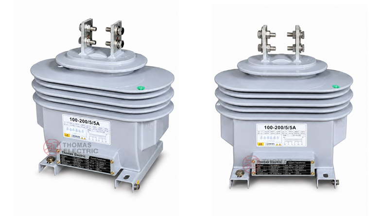
This series should be positioned as an outdoor dry-type alternative to oil-immersed CTs. Compared with oil-immersed outdoor transformers, the LZZBW series has no transformer oil, lower leakage risk and easier field maintenance. The front terminal box includes a wiring outlet hole for safer secondary cable connection, while the bottom plate provides grounding bolts and four mounting holes for stable outdoor installation.
Product Type


| Item | LZZBW-15 | LZZBW-24 |
|---|---|---|
| Product name | Outdoor Epoxy Resin Cast Current Transformer | Outdoor Epoxy Resin Cast Current Transformer |
| Installation | Outdoor | Outdoor |
| Structure | Pillar-type, fully enclosed | Pillar-type, fully enclosed |
| Insulation medium | Outdoor-grade epoxy resin | Outdoor-grade epoxy resin |
| Rated voltage class | 15kV / 17.5kV class | 24kV class |
| Rated insulation level | 17.5/38/75kV or 17.5/55/105kV by project requirement | 24/65/125kV |
| Rated frequency | 50Hz or 60Hz | 50Hz or 60Hz |
| Rated secondary current | 5A or 1A | 5A or 1A |
| Typical use | Outdoor metering, measurement and protection | Outdoor metering, measurement and protection |
Model Explanation

- L: Current transformer.
- Z: Pillar-type structure.
- Z: Epoxy resin cast insulation.
- B: With protection winding / metering and protection CT series.
- W: Outdoor type.
- 15: 15kV / 17.5kV class outdoor distribution system.
- 24: 24kV class outdoor distribution system.
- 5A or 1A: Rated secondary current option.
- Accuracy combination: Metering and protection combinations such as 0.2/10P10, 0.5/10P10, 0.2/10P15, 0.5/10P15, 0.2S/5P10 and related project-specific combinations.
Product Positioning
The LZZBW series is best described as an outdoor epoxy cast-resin CT for dry-type distribution metering and protection. It is not an indoor switchgear CT, and it is not an oil-immersed transformer. Its main value is outdoor dry insulation, fully enclosed epoxy body, safer secondary wiring access and simplified maintenance for exposed distribution installations.
| Positioning Point | Technical Meaning | Website Expression |
|---|---|---|
| Outdoor dry-type design | No transformer oil, epoxy resin insulation | Outdoor epoxy cast-resin CT for oil-free distribution metering |
| Multi-voltage platform | 15kV / 17.5kV and 24kV versions | One product family for different medium-voltage networks |
| Protection + metering | Metering accuracy and protection accuracy can be combined | Suitable for measurement, energy metering and relay protection |
| Outdoor terminal box | Front outlet hole supports secondary cable wiring | Safer field wiring and easier maintenance access |
| Bottom mounting structure | Grounding bolts and four mounting holes | Stable outdoor installation on brackets, platforms or substation structures |
Applications
- 15kV, 17.5kV and 24kV outdoor medium-voltage distribution systems
- Outdoor feeder metering and utility energy measurement
- Pole-mounted metering equipment and outdoor distribution cabinets
- Outdoor substations and compact substation incoming / outgoing feeders
- Relay protection circuits for distribution lines and transformers
- Industrial outdoor power distribution and renewable energy grid connection points
- Projects requiring oil-free outdoor instrument transformers
Features
- Outdoor epoxy vacuum casting: Fully enclosed epoxy resin insulation supports outdoor dielectric performance and mechanical strength.
- Oil-free dry-type structure: Reduces oil leakage risk and simplifies field maintenance compared with oil-immersed CTs.
- Multi-voltage coverage: LZZBW-15 covers 15kV / 17.5kV class systems, while LZZBW-24 covers 24kV class systems.
- Metering and protection options: Accuracy combinations can support current measurement, revenue metering and relay protection.
- Safe wiring design: The terminal box front outlet hole matches the cable outlet for safer and more reliable secondary wiring.
- Stable outdoor mounting: Grounding bolts and four bottom mounting holes support secure installation on outdoor structures.
Operating Principle
The LZZBW outdoor current transformer converts medium-voltage primary current into a standardized secondary current signal, normally 5A or 1A. The secondary signal is supplied to meters, protection relays and monitoring devices. The epoxy resin cast body provides electrical insulation between the high-voltage primary circuit and the low-voltage secondary circuit.
For metering use, the CT must maintain ratio accuracy and phase displacement within the selected accuracy class and rated burden. For protection use, the protection winding must provide reliable output during fault-current conditions. Therefore, current ratio, secondary current, rated output, accuracy class and short-time withstand current should be confirmed together before ordering.
Technical Data
| Parameter | LZZBW-15 | LZZBW-24 |
|---|---|---|
| Product type | Outdoor epoxy resin cast current transformer | Outdoor epoxy resin cast current transformer |
| Rated voltage class | 15kV / 17.5kV class | 24kV class |
| Rated insulation level | 17.5/38/75kV or 17.5/55/105kV by project requirement | 24/65/125kV |
| Rated frequency | 50Hz or 60Hz | 50Hz or 60Hz |
| Rated primary current | 5A–600A reference range; customizable | 10A–2000A reference range; customizable |
| Rated secondary current | 5A or 1A | 5A or 1A |
| Accuracy class combination | 0.2/10P10, 0.5/10P10, 0.2/10P15, 0.5/10P15 | 0.2S/0.5/5P10, 0.2S/0.5/5P20, 0.2S/0.5/5P30 and project-specific combinations |
| Rated output | 10/15VA or 15/15VA reference | 20/20/100, 20/20/60, 20/20/40, 20/20/25, 30/30/120 and related combinations |
| Power factor | cosφ = 0.8 lag reference | cosφ = 0.8 lag reference |
| Structure type | Pillar-type, fully enclosed | Pillar-type, fully enclosed |
| Housing material | Outdoor-grade epoxy resin, UV-resistant and tracking-resistant | Outdoor-grade epoxy resin, UV-resistant and tracking-resistant |
| Ambient temperature | -25°C to +40°C reference | -25°C to +40°C reference |
| Installation | Outdoor | Outdoor |
| Applicable standards | IEC 61869-1, IEC 61869-2, GB/T 20840.1, GB/T 20840.2 | IEC 61869-1, IEC 61869-2, GB/T 20840.1, GB/T 20840.2 |
Selection Table
The following selection table is organized for website display. Long headings and accuracy-class cells are split into multiple lines to avoid layout overflow on product pages.
| Model | Rated Primary Current (A) |
Accuracy Class Combination |
Rated Output (VA) |
Rated Short-Time Thermal Current |
Rated Dynamic Current |
|---|---|---|---|---|---|
| LZZBW-15 | 5–600 | 0.2/10P10 0.5/10P10 0.2/10P15 0.5/10P15 |
10/15VA 15/15VA |
By current ratio and project requirement | By current ratio and project requirement |
| Customized range | Metering + protection combinations | By agreement | By agreement | By agreement | |
| LZZBW-24 | 10–40 | 0.2S/0.5/5P10 0.2S/0.5/5P15 0.2S/0.5/5P20 0.2S/0.5/5P30 0.2S/0.5/5P10/5P10 0.2S/0.5/5P15/5P15 0.2S/0.5/5P20/5P20 0.2S/0.5/5P30/5P30 |
20/20/100 20/20/60 |
150 × I1n | 375 × I1n |
| 50–100 | 20/20/60 20/20/40 |
200 × I1n | 500 × I1n | ||
| 150–250 | 20/20/25 | 32kA | 80kA | ||
| 300–400 | 20/20/40 20/20/30/30 |
50kA | 125kA | ||
| 500–600 | 20/20/20 20/20/10/10 |
63kA | 160kA | ||
| 750–800 | 30/30/120 30/30/80 |
80kA | 200kA | ||
| 1000–2000 | 30/30/50/50 30/30/30/30 30/30/25/25 30/30/15/15 |
100kA | 250kA |
Note: The table is for preliminary selection. Final current ratio, rated burden, accuracy class, protection class, short-time thermal current, dynamic current and terminal arrangement shall be confirmed according to the nameplate, approved drawing and factory test report.
Normal Operating Conditions
| Parameter | Value |
|---|---|
| Installation place | Outdoor |
| Maximum ambient temperature | +40°C reference |
| Minimum ambient temperature | -25°C reference |
| Daily average temperature | ≤ +30°C reference |
| Altitude | ≤ 1000m under standard service conditions; higher altitude by agreement |
| Atmospheric condition | No severe pollution, corrosive gas or explosive atmosphere beyond design limits |
| Outdoor exposure | Suitable for UV, humidity and tracking-resistant outdoor insulation applications |
Installation and Dimensions

The LZZBW series is installed outdoors on a stable mounting plate, bracket, pole-mounted support or substation structure. The bottom plate includes four mounting holes for mechanical fixing and grounding bolts for safe earthing. The front hole of the terminal box should be aligned with the secondary cable outlet, allowing the secondary wiring to enter safely and reliably.
| Installation Item | Recommended Check Point |
|---|---|
| Mounting base | Confirm the four mounting holes, base dimensions and support strength before installation. |
| Primary terminal | Check P1 / P2 direction, conductor connection method and electrical clearance. |
| Secondary terminal box | Align the wiring outlet hole with the secondary cable route and seal the cable entry properly. |
| Grounding | Use the grounding bolts on the bottom plate and connect the CT base to the station grounding system. |
| Outdoor insulation | Confirm creepage distance, pollution level, UV exposure and tracking-resistant requirements. |
| Maintenance access | Reserve space for terminal inspection, nameplate reading and cable maintenance. |
Windings & Terminal Marking
The primary terminals are normally marked P1 and P2. The secondary terminals are marked according to the number of secondary windings and the approved wiring diagram. For metering and protection configurations, each secondary group should be assigned to a clear function before production.
| Terminal | Function | Application Note |
|---|---|---|
| P1 / P2 | Primary terminals | Used for primary current direction and polarity reference. |
| 1S1 / 1S2 | First secondary winding | Usually assigned to metering or current measurement. |
| 2S1 / 2S2 | Second secondary winding | Usually assigned to relay protection. |
| 3S1 / 3S2 | Additional secondary winding when specified | Used for backup protection or independent monitoring circuit. |
| Grounding point | Secondary / base grounding reference | One point of the secondary circuit and the CT base should be grounded according to project practice. |
Standards and Compliance
For new international documentation, the LZZBW-15 / LZZBW-24 series should be specified according to IEC 61869-1 and IEC 61869-2. For Chinese standard documentation, GB/T 20840.1 and GB/T 20840.2 can be used. Older catalogue references such as IEC 60044-1 may be retained only when required by a tender or comparison document.
Safety Notes
- Confirm voltage class, insulation level, current ratio, rated secondary current, accuracy class and rated output before installation.
- Verify P1 / P2 polarity and the secondary terminal marking before connecting meters or protection relays.
- Ground the CT base and one point of the secondary circuit according to the project grounding design.
- The CT secondary circuit must not be open-circuited while primary current is flowing.
- Before disconnecting meters, relays or test equipment, short-circuit the secondary circuit with an approved shorting device.
- Seal the terminal box cable outlet after secondary wiring to prevent moisture ingress.
- Do not install the CT in an environment with severe chemical corrosion, explosive gas or mechanical impact beyond the product design limits.
- Installation and commissioning shall be performed by qualified medium-voltage electrical personnel.
Selection Guide
- Confirm voltage level: Use LZZBW-15 for 15kV / 17.5kV systems and LZZBW-24 for 24kV systems.
- Confirm outdoor dry-type requirement: Select this series where an oil-free outdoor CT is preferred for maintenance or environmental reasons.
- Select current ratio: Choose the primary current according to feeder load, metering range and protection settings.
- Choose secondary current: Use 5A for conventional meters and relays; use 1A when long secondary wiring or lower cable burden is required.
- Define accuracy combination: Use 0.2S / 0.2 for higher metering accuracy and 5P / 10P for relay protection.
- Check rated burden: Calculate the total burden of meters, relays, terminal blocks and secondary cables.
- Approve installation details: Confirm base mounting holes, grounding bolts, terminal box outlet direction and wiring diagram before production.